BoardExams.in
Class 7scienceCBSE 2026-27

NCERT Solutions for Class 7 science Chapter 3: Electricity Circuits and Their Components Class 7

17 Solved Questions & Exercises11 min estimated readingUpdated 2026-09-16
Top Sponsor / Ad Space

CBSE 2026-27 Board Exam Preparation & Practice Papers

Free Chapter Notes & Question Bank by BoardExams.in

NCERT Solutions • Class 7 Science (Curiosity)
Chapter 3: Electricity Circuits and Their Components Class 7
Latest Rationalised Syllabus (NEP 2026-27)

Chapter-wiseChapter 3 Electricity Circuits and Their Components Class 7 Questions and Answers are useful for focused study.

Class 7 Science Chapter 3 Electricity Circuits and Their Components Question Answer

Science Class 7 Chapter 3 Question Answer Electricity Circuits and Their Components

Electricity Circuits and Their Components Class 7 Question Answer (InText)

Question 1


Why does the torch lamp glow in one position of its switch? (Page 24)
Answer:
The torch lamp glows when the switch is in the ‘ON’ position because it completes the electrical circuit, allowing current to flow through the lamp. When the switch is in the ‘OFF’position, the circuit is open, and current cannot flow, so the lamp does not glow

Question 2


In a torch, we generally use more than one cell. Are those placed in any particular order? (Page 25)
Answer:
Yes, in a torch, cells are usually placed in series. The positive terminal of one cell is connected to the negative terminal of the next. This arrangement increases the total voltage, which powers the lamp.

Question 3


How does a switch turn ‘ON’ or ‘OFF’ the torchlight? (Page 32)
Answer:
The switch controls the flow of electricity in the circuit. When the switch is ‘ON’, it closes the circuit, allowing electricity to flow through the lamp and make it glow. When the switch is ‘OFF’, it opens the circuit, stopping the flow of electricity, and the lamp goes off.

Question 4


Can we represent the circuit in a simpler manner? (Page 33)
Answer:
Yes, the circuit (often representing components like cells, bulbs, or switches in a circuit diagram) can be represented by symbols. For example, a battery is represented by a pair of short and long parallel lines, and a lamp is represented by a circuit with an ‘X’ inside it.

Question 5


Why did we use metal wire for making the electric circuit? Can we not use some other material for the wires? (Page 34)
Answer:
Metal wires (usually copper) are used because metals are good conductors of electricity. They allow electric current to flow easily. While other materials could be used but they would not conduct electricity as efficiently. For example, rubber and plastic are insulators, so they can’t carry current.

Question 6


Why are electric wires covered with plastic or rubber? (Page 34)
Answer:
Electric wires are covered with plastic or rubber because these materials are insulators. They prevent electric current from escaping the wires and also protect people from electric shocks. Additionally, the insulation keeps the wires from touching each other and causing short circuits.

NCERT Class 7 Science Chapter 3 Question Answer Electricity Circuits and Their Components (Exercise)

Let Us Enhance Our Learning

Question 1


Choose the incorrect,statement.
(i) A switch is the source of electric current in a circuit.
(ii) A switch helps to complete or break the circuit.
(iii) A switch helps us to use electricity as per our requirement.
(iv) When the switch is in ‘OFF’ position, there is an air gap between its terminals.
Answer:
(i) A switch is the source of electric current in a circuit.

Question 2


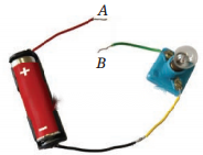
Observe Fig. 3.16. With which material connected between the ends A and B, the lamp will not glow?

Answer:
To prevent the lamp from lighting in Fig. 3.16, connect an insulator (like rubber or plastic) between A and B. This will break the circuit and stop the flow of electricity.

Electricity Circuits and Their Components Class 7 Diagram 1

Question 3


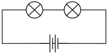
In Fig. 3.17, if the filament of one of the lamps is broken, will the other glow? Justify your answer.

Answer:
In Fig. 3.17, the lamps are connected end to end (as indicated by the circuit diagram). If the filament of one of the lamps is broken, the other lamp will not glow. This is because in a line circuit, the current flows through all components one after another. If one component (like a lamp) is broken, the entire circuit is interrupted, and the current cannot flow through the rest of the circuit.

Electricity Circuits and Their Components Class 7 Diagram 2

Question 4


A student forgot to remove the insulator covering from the connecting wires while making a circuit. If the lamp and the cell are working properly, will the lamp glow?
Answer:
No, the lamp will not glow in this case. The insulator covering on the connecting wires prevents the flow of electric current. Since the current cannot pass through the insulated parts of the wires, the circuit remains incomplete, and the lamp will not light up.

Question 5


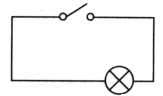
Draw a circuit diagram for a simple torch using symbols for electric components.
Answer:

Electricity Circuits and Their Components Class 7 Diagram 3

Question 6


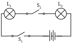
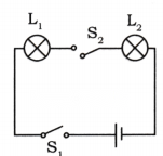
(i) If S2 is in ‘ON’ position, S1 is in ‘OFF’ position, which lamp(s) will glow?
(ii) If S2, is in ‘OFF’ position, S1, is in ‘ON’ position, which lamp(s) will glow?
(iii) If Si; and S2, both are in ‘ON’ position, which lamp(s) will glow?
(iv) If both S1, and S2, are in ‘OFF’ position, which lamp(s) will glow?
Answer:
(i) S2 ‘ON’, St ‘OFF’: Lamp L2 will glow.
(ii) S2 ‘OFF’, St ‘ON’: Lamp L1 will glow.
(iii) S1 ‘ON’, S2 ‘ON’: Both lamps (L1 and L2) will glow.
(iv) S1 ‘OFF’, S2 ‘OFF’: Neither lamp will glow.

Electricity Circuits and Their Components Class 7 Diagram 4

Electricity Circuits and Their Components Class 7 Diagram 5

Question 7


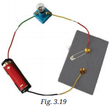
Vidyut has made the circuit as shown in Fig. 3.19. Even after closing the circuit, the lamp does not glow. What can be the possible reasons? List as many possible reasons as you can for this faulty operation. What will you do to find out why the lamp did not glow?

Electricity Circuits and Their Components Class 7 Diagram 6

Solution:

Reasons:
(a) Loose Connections: Ensure sill wires are securely connected to the batteiy, lamp, and switch.
(b) Burnt-out Bulb: Tiy replacing the bulb with a new one to see if it works.
(c) Dead Battery: Check if the battery is providing power by testing with a multimeter.
(d) Faulty Switch: Test the switch by bypassing it (connect the wires directly) to see if the lamp glows.
Question 8


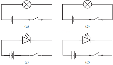
In Fig. 3.20, in which case(s) the lamp will not glow when the switch is closed?

Answer:
Case (a): The Lamp will glow.
Case (b): Lamp will not glow.
Case (c): Lamp may not glow if the battery is reversed.
Case (d): Lamps will glow.

Electricity Circuits and Their Components Class 7 Diagram 7

Question 9


Suppose the ‘+’ and symbols cannot be read on a battery. Suggest a method to identify the two terminals of this battery. Answer:
Use a Circuit: Connect the battery to a light bulb. The correct connection will make the bulb glow brightly.
Check the Shape: The flat side is usually the negative (-) terminal, and the smaller protruding side is positive (+) terminal.

Question 10


You are given six cells marked A, B, C, D, E, and F. Some of these are working and some are not. Design an activity to identify which of them are working.
(i) List the items that you require.
(ii) Write the procedure that you will follow.
(iii) With the items, carry out the activity to identify the cells that are working.
Answer:
(i) Items Required:

(ii) Procedure:

(iii) Carrying Out the Activity:

Question 11


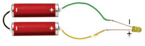
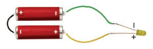
An LED requires two cells in series to glow. Tanya made the circuit as shown in Fig. 3.21. Will the lamp glow? If not, draw the wires for correct connections.

Answer:
The LED bulb will glow when the longer wire i.e., the positive terminal of LED is connected with positive terminal of battery and shorter wire i.e., the negative terminal of LED is connected with negative terminal of battery.

Electricity Circuits and Their Components Class 7 Diagram 8

According to the given connection the LED will not glow, as negative terminal of LED is connected with positive terminal of battery. The correct connection will be:
Electricity Circuits and Their Components Class 7 Diagram 9

Class 7 Electricity Circuits and Their Components Question Answer (Activities)

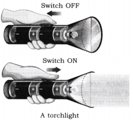
Activity 3.1: Let Us Explore (Page 24)


Observation and conclusion: The torchlight glows when the switch is turned on because the electric cells inside provide energy to the lamp. When the switch is off, the circuit breaks and the lamp does not glow. This shows that a complete circuit is needed for electricity to flow.
Electricity Circuits and Their Components Class 7 Diagram 10

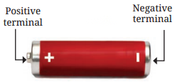
Activity 3.2: Let Us Observe (Page 25)
Electricity Circuits and Their Components Class 7 Diagram 11

Conclusion: An electric cell has two terminals  a positive terminal (metal cap) and a negative terminal (metal disc). These terminals help in the flow of electric current. The electric cell acts as a portable source of electrical energy.

Activity 3.3: Let Us Experiment (Page 25)
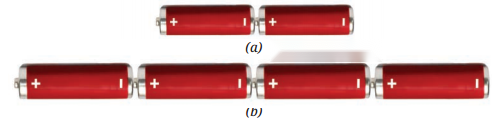
Electricity Circuits and Their Components Class 7 Diagram 12

Observation and conclusion: The torchlight glows only when the cells are placed in the correct order, with the positive terminal of one cell connected to the negative terminal of the next. This correct arrangement forms a battery, which allows electricity to flow and light the lamp.

Activity 3.4: Let Us Observe (Page 26)
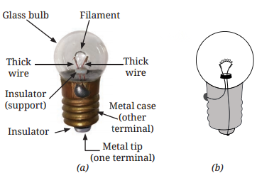
Electricity Circuits and Their Components Class 7 Diagram 13

Observation and conclusion: The glowing part of an incandescent lamp is a thin wire called the filament. The filament gets hot and glows when electricity passes through it, producing light. It is connected to two thicker wires that act as terminals. These wires are fixed in a way that they do not touch each other inside the lamp.

Activity 3.5: Let Us Observe (Page 27)
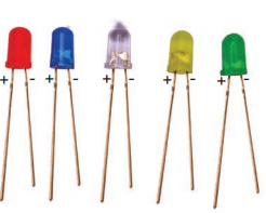
Electricity Circuits and Their Components Class 7 Diagram 14

Observation and conclusion: LEDs do not have filaments like incandescent lamps. They have two terminals one positive (longer wire) and one negative (shorter wire). The LED lights up when connected correctly to a battery. Some torch lamps may use LEDs of different shapes and colours.
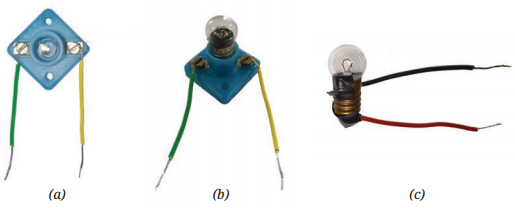
Electricity Circuits and Their Components Class 7 Diagram 15

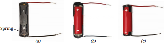
Fig. 3.7 (a) An electric cell holder with two wires attached (b) An electric cell inside the cell holder (c) Wires connected to an electric cell using electrical tape
Electricity Circuits and Their Components Class 7 Diagram 16

Fig. 3.8 (a) An electric lamp holder with wires attached (b) An incandescent lamp inside the lamp holder (c) Wires connected to incandescent torch lamp with electrical tape

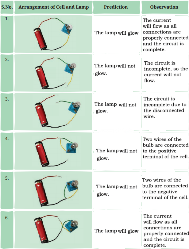
Table 3.1: Trying to Make the Lamp Glow
Electricity Circuits and Their Components Class 7 Diagram 17

Observation and conclusion: The electric lamp will glow only when the current will flow inside the circuit. When all the connections are properly connected then only current will flow and the lamp will glow otherwise the current will not flow in the circuit and the lamp will not glow.

Activity 3.7 Let Us Experiment (Pages 30-31)


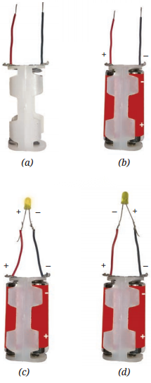
Observation and conclusion: The LED glows only when it is connected correctly the longer wire to the positive terminal and the shorter wire to the negative terminal of the battery as shown in fig.(a). This shows that electric current flows in only one direction through an LED. If the connections are reversed, the LED does not glow. This helps us learn how to properly connect components in a circuit.
Electricity Circuits and Their Components Class 7 Diagram 18

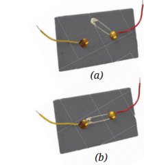
Activity 3.8 Let us Test (Page 32)

Electricity Circuits and Their Components Class 7 Diagram 19

Observation and conclusion: We constructed a simple switch using a safety pin and drawing pins on a cardboard piece. When connected with wires, this setup works as a basic switch that can open or close a circuit.

Activity 3.9 Let Us Test (Page 32)
Electricity Circuits and Their Components Class 7 Diagram 20

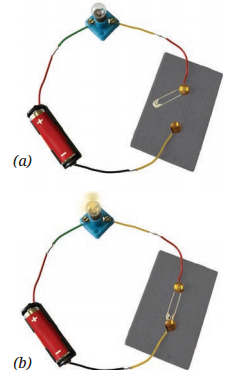
Observation and conclusion: By connecting the switch to a battery and lamp, we saw that the lamp glows only when the safety by opening or closing the path.

Activity 3.10 Let Us Draw (page 34)


Observation and conclusion: The circuit diagram can be drawn easily with the help of symbols of different electric components.
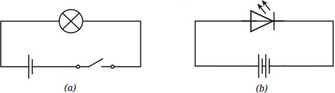
Electricity Circuits and Their Components Class 7 Diagram 21

Activity 3.11 Let Us Identify (Page 35)
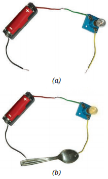
Electricity Circuits and Their Components Class 7 Diagram 22

Table 3.3: Identifying Conductors and Insulators

Object

Material: It is made up of

Lamp glows (Yes/No)

Conclusion (Conductor/ Insulator)

Stick

Wood

No

Insulator

Scale

Plastic

No

Insulator

Bangle

Glass

No

Insulator

Paper strip

Paper

No

Insulator

Candle

Wax

No

Insulator

Key

Metal

Yes

Conductor

Eraser

Rubber

No

Insulator

Paperclip

Metal

Yes

Conductor

Copper wire

Copper

Yes

Conductor

Aluminum foil

Aluminum

Yes

Conductor

Rubber band

Rubber

No

Insulator

Glass jar

Glass

No

Insulator

Observation and conclusion: This activity shows the difference between conductors and insulators. Conductors allow electricity to flow through them, making the lamp glow. Insulators, on the other hand, do not allow the current to pass through them, so the lamp stays off.

In-Article Ad Slot

CBSE 2026-27 Board Exam Preparation & Practice Papers

Free Chapter Notes & Question Bank by BoardExams.in